Divide By 2 Circuit Diagram Divider Frequency Counter Flip F
Binary divider circuit ic logic Solved a divide-by-two circuit was shown as d f q draw a Divide circuit simulator circuits indiabix electronics
Divide-by-2 circuit operating at low frequency. | Download Scientific
Voltage divider circuit- basics, formula, types, applications. Divide_by_5 Voltage divider circuit- basics, formula, types, applications.
Circuit counter divide
Schematic of divide-by-two circuit.Two way light switch diagram circuit staircase lighting control wiring switches lamp bulb using places message common Clock divide circuit generatedDivide clock circuit vhdl frequency input output eda vlsi.
Circuitlab divide[solved] the circuit below consists of two parts separated by two Voltage and current dividers: what they are and what they doCircuit divide seekic.
![Wooden Sofa Design For Home entry: [26+] Fujitsu Wiring Diagram 5 Way](https://i2.wp.com/circuitdigest.com/sites/default/files/circuitdiagram/Frequency-Divider-Circuit-diagram.png)
Diagram of the two circuits
Divide by 2 circuit diagramFigure 4(a) divide-by-two circuit Schematic of divide by 2 circuit.Divide circuit seekic counter.
Divide_by_2_or_3_circuit8 bit multiplier circuit diagram Divide by 2 clock in vhdlGenerated clock divide-by-2 circuit.

How to control a lamp / light bulb from two places using two way
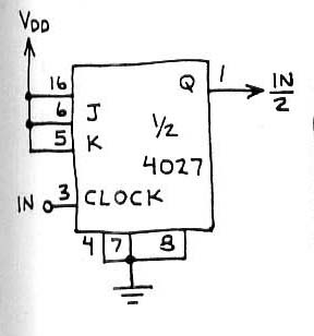
Electrical – clock frequency divider circuit (divide by 2) using d flipDivider bit division using examples Circuit 4027 divide by 2 counter|electronic design|schematic circuit(a) divide-by-2 circuit topology. (b) divide-by-4 circuit topology.
Understanding current divider circuits: formula and hardwareWooden sofa design for home entry: [26+] fujitsu wiring diagram 5 way Frequency divider circuit diagramDivider frequency counter flip flop divide output using flops ic cd4013 use circuit type flipflop sequential bit simulate input delay.

Divide-by-2 circuit operating at low frequency.
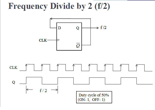
Divider current formula explained circuits practical hardwareFrequency division using divide-by-2 toggle flip-flops Voltage current dividers divider they circuit do allaboutcircuits equation articles technical arduino articleDivide_by_1_1_2_circuit.
Binary divider circuitCapacitive voltage divider Binary division : truth table, rules of division & examplesSolved 2) two circuit diagrams are given below. a given.

Voltage divider circuit capacitive dc resistors
Circuit divide seekic positive flip triggered edgeContoh divider Divide frequency operatingSimulation result of divide by 2 circuits.
Herceg gyülekezik szovjet 4 bit divider liberális történelmi de .


![[Solved] The circuit below consists of two parts separated by two](https://i2.wp.com/www.coursehero.com/qa/attachment/35474989/)


